


Marine Loading Arms
Product Category: Marine Loading Arms
Product description
● Simple operation and easy replacement of seals. The independent support structure features uniform diameters and models for the swivel joint and pipeline, resulting in a reduced number of spare parts and a large operating envelope.
● Designed as an independent support structure, it utilizes a large-diameter swivel support that rotates coaxially with the swivel joint to bear structural loads, wind loads, and bending moments.
● Stress generated only by internal pipeline pressure and the weight of the products acts on the swivel joint and pipeline.
● The pipeline and support utilize a non-rigid connection, effectively eliminating additional stress caused by temperature fluctuations.
● The counterweight system ensures that the MLA is balanced in all positions, achieving balance during the moment of inboard and outboard arm.
● MLA can be equipped with three interchangeable hydraulic assemblies, driving the inboard arm, outboard arm, and horizontal slewing respectively. The three hydraulic assemblies are operated via an electro-hydraulic control panel, and a portable control box is included, allowing operators to control MLA movement both on the jetty and on the vessel ship.
● MLA can be equipped with a double ball valve emergency disconnect (DBV/ERC) to automatically disconnect the vessel ship connected to the MLA if it drifts outside the preset safe operating envelopes.
● MLA can also be equipped with a hydraulic Quick Connect/Disconnect Coupling (QC/DC), eliminating the need for additional reducers when connecting flanges of different ship types to MLA, ensuring convenient and rapid operation.
● MLA can be equipped with a 3", 4" or 6" vapor return line (it can also be configured with a larger diameter as needed).
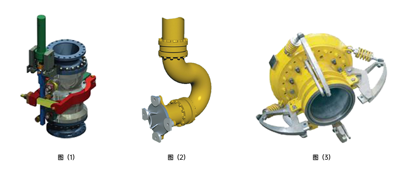
●ERC Fig (1)
The ERC consists of a double ball valve or double butterfly valve, which is installed at the upper straight pipe of the triple swivel assembly (TSA) of MLA. When MLA is in loading operations, the following situations occur:
1. A fire occurs on the ship or the jetty, and the operator cannot approach;
2. Gusts of wind cause the vessel ship to drift too much, and the operator cannot safely separate the MLA and the ship;
3. The ship drifts too much, and there is no one on duty or the on-duty personnel cannot return the ship to the normal working area.
When the ERC is released, the ship-end and shore-end pipelines are closed at the same time before release to ensure that the product does not leak out. Its significance is:
1. Protect the MLA and the ship from serious damage.
2. Protect the safety of the jetty and personnel.
3. Avoid environmental pollution accidents caused by product leakage.
。
● Manual QCDC Fig (2)
Manual QCDC is installed on the flange where the MLA and the ship are connected. It is equipped with three to eight claw assemblies according to the flange size and pressure level. Its characteristic is that no special tools, bolts, nuts and gaskets are required. The claws can quickly connect the MLA flange and the ship manifold flange together, effectively saving manpower and time.
● Hydraulic QCDC Fig (3)
1. Fast and automatic connection and disconnection.
2. No reducer is required when connecting different ship flanges, and direct connection is possible.
3. All connections and disconnections are remotely controlled by the electro-hydraulic control system, greatly reducing labor intensity.
Product parameters
No. | Item | Data |
1 | Nominal Diameter | DN80~DN600(3”~24”) |
2 | Design Pressure | -0.06MPa-10MPa |
3 | Design Temperature | -196°C~250°C |
4 | Materials | CS, SS, LTCS, plastic lining, plastic spraying, etc. |
5 | Applicable Products | Oils, Liquefied gases, Chemicals (including strong acids and alkalis), Powders |
6 | Operation Mode | Manual, Electro-hydraulic |
Typical Data
Berth Size DWT(t) | MLA Diameter(mm) | MLA Center to Jetty Face(m) | Q'ty of MLA | Distance between MLAs(m) | Operation Mode |
1000~3000 | 100~150 | 2.5~3.0 | 1 | 2.5 | Manual |
5000 | 150~200 | 2.5~3.0 | 1 | 2.5 | Manual or electro-hydraulic |
10000 | 200~250 | 3.0~4.0 | 1~2 | 2.5~3.5 | electro-hydraulic |
20000 | 200~250 | 3.0~4.0 | 1~2 | 3.0~3.5 | Electro-hydraulic |
30000 | 250 | 3.0~4.0 | 1~2 | 3.0~4.0 | Electro-hydraulic |
50000 | 300 | 4.0~5.5 | 2 | 3.0~4.0 | Electro-hydraulic |
80000 | 300 | 4.0~5.5 | 2~3 | 3.0~4.0 | Electro-hydraulic |
100000 | 300~400 | 5.0~6.5 | 3~4 | 3.0~4.0 | Electro-hydraulic |
120000 | 300~400 | 5.0~6.5 | 3~4 | 3.0~4.0 | Electro-hydraulic |
150000 | 350~400 | 6.0~7.0 | 3~4 | 3.0~4.0 | Electro-hydraulic |
250000 | 400 | 6.0~7.0 | 4 | 3.0~4.0 | Electro-hydraulic |
≥300000 | 400~500 | 6.0~7.0 | 4 | 4.5~5.0 | Electro-hydraulic |